The Siemens S7 Communication - Part 2 Job Requests and Ack Data
This article series introduces the Siemens S7 protocol in depth, the first part detailed the general communication scenario and packet structure. This part further examines the purpose and internal structure of the Job Request and Ack Data messages. These message types are discussed together because they are very similar and usually each Job Request results in an Ack Data reply.
The structure of the S7 PDU and the general protocol header is explained in the previous part. However, the parameter header is specific to the message type and for the Job and Ack Data messages it begins with a function code. The structure of the rest of the fields depend on this value. This function code determines the purpose of the message and serves as the basis of further discussion.
1. Setup Communication [0xF0]
Pcap: S300-setup-communication
This message pair (a Job and Ack Data response) is sent at the beginning of each session before any other messages could be exchanged. It is used to negotiate the size of the Ack queues and the max PDU length, both parties declare their supported values. The length of the Ack queues determine the number of parallel jobs that can be initiated simultaneously without acknowledgement. Both the PDU and queue length fields are big endian.
The parameter header is shown in the following diagram:

1.1 S7 Authentication and Protection
Pcap: s300-authentication
This is probably a good place to talk about the S7 authentication and protection mechanisms (even though they have nothing to do with the actual communication setup). There are three protection modes that can be set during configuration for the CPU.
- No protection: Just as one would expect no authentication is required.
- Write protection: For certain data write and configuration change operations authentication is required.
- Read/Write protection: Just like the previous one but certain read operations require authentication as well.
It must be noted that even if Read/Write protection is enabled there are certain operations that are allowed such as reading SZL Lists or reading and writing into Marker area. Other operations such as reading or writing Object/Function/Data Blocks should return a permission error.
There are two protection level sets associated with the CPU, the assigned protection level and the real protection level. The assigned protection level is the one set during configuration, while the real one is the current protection level applicable for the communication session.
During normal operation clients that need read/write privileges query the real and assigned protection levels, after the communication setup, through SZL reads (SZL ID: 0x0132 SZL Index: 0x0004). If authentication is required the password is sent to the device, in a userdata message, which lowers the effective protection level.
Just before anyone would think that this provides at least a tiny bit of security let me clarify that it is not. The password is six bytes and sent almost in the clear (XORed with constants and shifted). It is replayable and can be bruteforced. The protocol also provides no integrity or confidentiality protection, message injection and modification is possible. The general rule of thumb when it comes to S7 security is if you can ping the device you can own it.
It must be noted here that the S7-1200/1500 series devices use a slightly different approach, protection levels are handled a bit differently and the password sent is significantly longer (it is actually the hash of the password) but it is still constant and replayable.
2. Read/Write Variable [0x04/0x05]
Pcaps:
- s300-read-variable-simple
- s300-read-write-variable (multiple variable reads and writes with simple addressing)
- s400-read-write-variable-db (multiple variable reads and writes with database addressing)
Here is when things start to get a bit more complicated, I highly recommend looking at the provided pcaps while reading this section (wireshark2 comes with S7 dissector enabled by default). Data read and write operations are carried out by specifying the memory area of the variable, its address (offset) and its size or type. Before going into the protocol details I would like to briefly introduce the S7 addressing model.
Like mentioned previously variables are accessed by specifying their addresses, this address is composed of three main attributes. The memory area:
- Merker:[M] arbitrary marker variables or flag registers reside here.
- Data Block:[DB] DB areas are the most common place to store data required by the different functions of the device, these data block are numbered which is part of the address.
- Input:[I] digital and analog input module values, mapped into memory.
- Output:[Q] similarly memory mapped outputs.
- Counter:[C] values of different counters used by the PLC program.
- Timer:[T] values of different timers used by the PLC program.
There are other less common memory areas as well (such as local data [L] and peripheral access [P] and so on).
The type of the variable determines its length and how it should be interpreted. A few examples are:
- BIT:[X] a single bit.
- WORD: two bytes wide unsigned integer.
- DINT: four bytes wide signed integer.
- REAL: four bytes wide IEEE floating point number.
- COUNTER: counter type used by the PLC program counters.
An example address of a variable is DB123X 2.1 which accesses the second bit of the third byte of the Data Block #123.
After this short detour let’s go back to the protocol’s implementation of variable read/write. The S7 protocol supports querying multiple variable reads/writes in single message with different addressing modes. There are three main modes:
- any-type: This is the default addressing mode and it is used to query arbitrary variables. All three parameters (area, address, type) are specified for each addressed variable.
- db-type: This is special mode designed to address DB area variables, it is more compact than the any-type addressing.
- symbolic-addressing: This mode is used by the S7-1200/1500 series devices and allows the addressing of certain variables with their pre-defined symbolic names. This mode will not be covered in detail here.
For each addressing mode the Parameters header is structured in the same way:
- Function Code:[1b] constant value of 0x04 for read or 0x05 for write Jobs and replies.
- Item Count:[1b] number of following Request Item structures.
- Request Item: this structure is used to address the actual variables, its length and fields depend on the type of addressing being used. These items are only present in the Job request and are emitted from the corresponding Ack Data no matter what the addressing mode is or whether it is a read or write request.
The Data part of the S7 PDU varies based on the type (read/write) and the direction (Job/Ack Data) of the message:
- Read Request: the Data part is empty.
- Read Response: the Ack Data message’s Data part consists of Data Item structures, one for each of the Request Items present in the original request. These items contain the actual value of the read variable and the format depends on the addressing mode.
- Write Request: contains similar Data Items as the read response, one for each of the Request Items in the Parameter header. Similarly, these contain the variable value to be written on the slave device.
- Write Response: The Data part of the Ack Data message simply contains a one byte error code for each of the Request Items in the original Write Request. See the constants.txt for the error code values.
To sum it up, the Request Item always contains the description of the variables and multiple of these can be sent in the Job request while the Data Items contain the actual values of the described variables. The Data Item structures must begin on even bytes so if their length is an odd number and there is a following Data Item then they are padded with a zero byte.
What is left to be discussed is the format of the Request/Data Item structures. As previously mentioned they are dependent on the addressing mode being used so they are going to be introduced based on that.
2.1 Item Structures with any-type Addressing
The figure below shows the Request and Data Item structures:

The fields of the Request Item:
- Specification Type:[1b] this field determines the main type of the item struct, for read/write messages it always has the value 0x12 which stands for Variable Specification.
- Length:[1b] the length of the rest of this item.
- Syntax ID:[1b] this field determines the addressing mode and the format of the rest of the item structure. It has the constant value of 0x10 for the any-type addressing.
- Variable Type:[1b] is is used to determine the type and length of the variable (usual S7 types are used such as REAL, BIT, BYTE, WORD, DWORD, COUNTER, …).
- Count:[2b] it is possible to select an entire array of similar variables with a single item struct. These variables must have the same type, and must be consecutive in the memory and the count field determines the size of this array. It is set to one for single variable read or write.
- DB Number:[2b] the address of the database, it is ignored if the area is not set to DB (see next field).
- Area:[1b] selects the memory area of the addressed variable. See the constants.txt for the memory area constants.
- Address:[3b] contains the offset of the addressed variable in the selected memory area. Essentially, the addresses are translated to bit offsets and encoded on 3 bytes in network (big endian) byte order. In practice, the most significant 5 bits are never used since the address space is smaller than that.
As an example DBX40.3 would be 0x000143 which is
40 * 8 + 3.
Similarly the fields of the associated Data Item:
- Error Code:[1b] the return value of the operation, 0xff signals success. In the Write Request message this field is always set to zero.
- Variable Type and Count:[1b 2b] same as in the Request Item.
- Data: this field contains the actual value of the addressed variable, its size is
len(variable) * count.
2.2 Item Structures with db-type Addressing
I have only seen this type of addressing used with S400 series devices, however it might be supported by some S300 series PLCs as well. It is only used to access DB variables and provides an alternative to address multiple different variables within a single item in a more compact format. The figure below shows the Request and Data Item structures:

The fields of the Request Item:
- Specification Type:[1b] same as with any-type addressing.
- Length:[1b] the length of the rest of this item.
- Syntax ID:[1b] determines the addressing mode, has a constant value of 0xb0 for db-type.
- Number of Subitems:[1b] the number of following Subitems.
- Subitem:
- Size:[1b] specifies the number of bytes to read or write from the selected address.
- DB Number:[2b] the DB where the addressed variable resides.
- Address:[2b] byte offset of the variable into the given DB.
The fields of the Data Item:
- Error Code:[1b] the return value of the operation, 0xff signals success.
- Variable Type:[1b] always set to 0x09 (Octet String).
- Length:[2b] length of the remaining Subresponse data.
- Subresponse:
- Error Code:[1b] the return value associated with the Subitem request.
- Data: actual data to be read or written, interpreting this requires the corresponding Subitem.
3 Block Up/Download [0x1a-1f]
Pcaps:
This is where things start to get messy. First of all, in Siemens terminology a download is when the master sends block data to the slave and upload is the other direction. On the Siemens devices, program code and (most of) the program data are stored in blocks, these blocks have their own header and encoding format, which will not be discussed here in detail. From the protocol’s point of view they are binary blobs that need to be transported (for the interested reader the snap7 sources provide information on the block headers and their encoding).
There are seven different type of blocks recognised by Siemens equipment:
- OB: Organisation Block, stores the main programs.
- (S)DB: (System) Data Block, stores data required by the PLC program.
- (S)FC: (System) Function, functions that are stateless (do not have their own memory), they can be called from other programs.
- (S)FB: (System) Function Block, functions that are stateful, they usually have an associated (S)DB.
The purpose of these blocks are well described in the Siemens documentation.
These blocks are addressed with a special ASCII filename within the up/download request. This filename is structured in a following way:
- File Identifier:[1 char] as far as I know this always has the value of ‘_’.
- Block Type:[2 chars] determines the block types, see the constants.txt for concrete values.
- Block Number:[5 chars] the number of the given block in decimal format.
- Destination File System:[1 char] this field can either have the value ‘A’ for Active or ‘P’ for Passive file systems. Blocks copied to the active file system are chained immediately, which means they are in effect as soon as the PLC execution resumes. On the other hand, blocks copied to the passive file system need to be activated first.
An example filename is _0800001P which is used to copy OB 1 to or from the passive file system.
** Let me make a quick note on block encoding and content protection. There are two measures in place to protect the content of programs and data on the devcies and allow the distribution of program libraries. The first one is called know-how protection, which if set prevents STEP7 or TIA showing the actual content of the block. Unfortunately, this is trivial to bypass, as it is just two bits set in the header of the blocks and can easily be cleared. The other protection measure is block “encryption”, which in reality is just an obfuscation with linear transformations (bytewise xoring and rotating with constants), again should be trivial to bypass. So do not rely on these “security” mechanisms to protect your know-how. Otherwise the data blocks contain the raw, initialized image of the memory. Program blocks contain the MC7 (Machine Code 7) binary instructions. **
Uploading and downloading blocks involves 3-3 different types of message pairs. These are listed below with the associated function codes:
- Request Download - 0x1a
- Download Block - 0x1b
- Download Ended - 0x1c
- Start Upload - 0x1d
- Upload Block - 0x1e
- End Upload - 0x1f
The structure of these messages are pretty simple, however the message sequence (especially for download) needs a bit of explaining.
3.1 Upload Block
The upload block sequence is fairly intuitive, it is presented below:
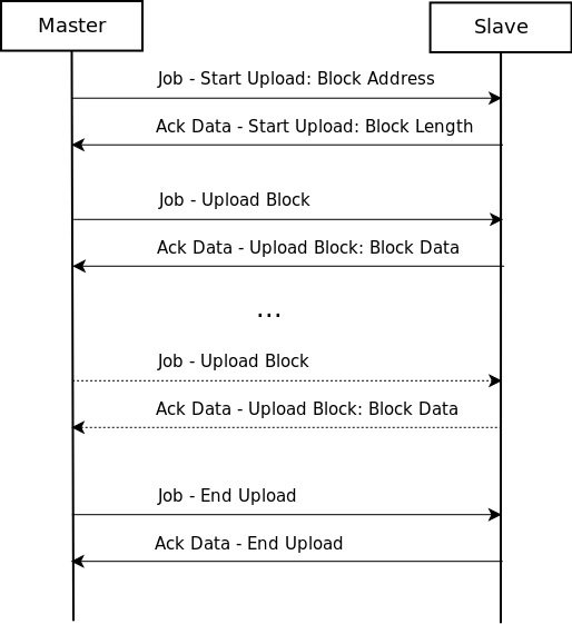
In the Ack Data - Start Upload message the slaves tells the length of the block and then the master keeps sending Job - Upload Block messages until receives all the bytes. Finally it closes the upload sequence with a Job - End Upload message. The actual data of the block is sent by the slave in the Ack Data - Upload Block messages.
Job - Start Upload Parameter Header:
- Function Code:[1b] 0x1d for Start Upload.
- Function Status:[1b] only used in the Upload message, set to 0x01 if more data is to be sent.
- Unknown:[2b] always 0x0000.
- Session ID:[4b] a unique id associated with each upload sequence, it is set in the Ack Data - Start Upload message.
- Filename Length:[1b] length of the following filename.
- Filename: the filename that identifies the block as introduced above.
Ack Data - Start Upload Parameter Header:
- Function Code:[1b] 0x1d for Start Upload.
- Function Status:[1b] same as above.
- Unknown:[2b] always 0x0100.
- Session ID:[4b] the Session ID is set here, consecutive messages use the same value.
- Length String Length:[1b] length of the following Block Length String.
- Length String: the decimal length of the block encoded as an ASCII C string (don’t ask me why…).
Job - Upload Parameter Header:
- Contains the Function Code (0x1e), Function Status, Unknown (0x0000) and Session ID fields as discussed above.
Ack Data - Upload Parameter and Data Parts:
- Function Code:[1b] 0x1e for Upload.
- Function Status:[1b] set to 0x01 if more data is to be sent.
- Data part:
- Length:[2b] the length of the Block Data.
- Unknown:[2b] always 0x00fb.
- Block Data: part of the uploaded data block.
Job - End Upload Parameter Header:
- Contains the Function Code (0x1f), Function Status, Unknown (0x0000) and Session ID fields as discussed above.
Ack Data - End Upload Parameter Header:
- Simply contains the Function Code (0x1f)
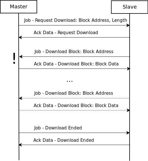
3.1 Download Block
The key difference between upload and download is that during download the direction of the communication changes and the slave becomes the master (well sort of). After the initial Request Download exchange the slave sends the Job messages and the master replies with Ack Data, this is the only exception to the “slave only replies” rule. After all the bytes are sent the master (the original) sends the Download Ended Job to close the download session. See the sequence diagram below.
The structure of the actual messages are really similar to the upload messages so I am only going to introduce the differences. For accurate syntax description open the example pcap in wireshark.
The Job - Request Download message contains two extra fields, the Block Length of the downloaded block and the Payload Length (the length without the block header) of the block. Both of these fields are decimal numbers encoded as ASCII strings. The response Ack Data - Request Download simply contains the Function Code.
Another significant difference is that, although the Session ID field is present it is not used (remains 0x00000000) instead the Filename is transmitted in each Job - Download Block. The structure of the rest of the messages is same as discussed before.
4 PLC Control [0x28]
Pcaps:
- s300-control-commands (Copy Ram to Rom, Compress Memory, Start PLC)
- s300-copy-ram-to-rom
- s300-activate-blocks
- s300-delete-blocks (Activate/Delete Block, Start PLC)
(try using the s7comm.param.func == 0x28 wireshark filter to find the PLC Control messages)
PLC control messages are used to execute different routines on the slave device that modify its execution/memory state. Such commands are used to start or stop the PLC control program’s execution, activate or delete program blocks on the device or save its configuration to persistent memory. The structure of these messages are fairly simple, they are going to be explained without discussing the exact details (for that see the attached captures).
The Job - PLC Control message consists of two main parts, the ASCII name of the called method and its parameter (also encoded as an ASCII string). The method name is structured in a similar manner as the file names introduced in the block transfer section. The parameters depend on the method type and they can be thought of as an argument to it. The Ack Data message simply contains the PLC Control function code.
Some example function names and their associated parameters:
_INSE: activates a downloaded block on the device, the parameter is the name of the block (e.g. OB1)._DELE: removes a block from the file system of the device, the parameter is again the name of the block.P_PROGRAM: sets the run state of the device (start, stop, mem reset). It is sent without parameter to start the device, however stopping the plc program uses a different function code (see next section)._GARB: compresses PLC memory._MODU: copy ram to rom, the parameter contains the file system identifiers (A/E/P).
5 PLC Stop [0x29]
Pcap s300-stop-program
The PLC Stop message is essentially the same as the PLC Control message. The only difference is that there is no parameter in the message and the routine part is always set to P_PROGRAM. I have no idea why it has its separate type instead of using a parameter to determine whether it is a start or stop message.
Outro
Well, this blog post grew way longer than I originally planned it to be, but I hope it will be useful for some. This might be obvious now, but the S7 protocol is not a well designed one. It was originally created to simply query register values, which it did kind of all right, but then functionality was kept being added until it became this monstrosity. It is filled with inconsistencies and unnecessary redundancies and it only gets worse with Userdata messages. These irregularities and design flaws become way more obvious (and annoying) while trying to write a parser for the protocol.
TL;DR
If S7 was a car it would probably look like this:

Update 2018-04-08:
- Corrected error about address encoding